Slow-Flight
Newbie
Hey really like my fan set up, and I am going to try some of those painting methods you got going there Dan.
I havnt tried anything like that.
I havnt tried anything like that.
Discover new ways to elevate your game with the updated DGCourseReview app!
It's entirely free and enhanced with features shaped by user feedback to ensure your best experience on the course. (App Store or Google Play)


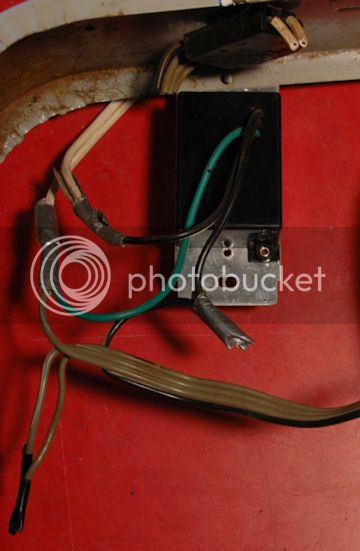
... make sure to work on this and any electrical project while the power is disconnected. It's hard to throw a disc if all you have are claws.
Dan, how much more would jtreadwell's idea of spin painting an entire disc front and back cost to do? I'm really interested in getting that done
Rayne that's sweet, nice use of the technique!
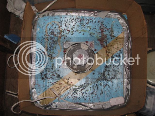
I'm struggling with the bottom at the moment so it won't be me doing it. I'm just putting a duct tape roll on top of the fan's center part to cover the "nose cone", it works ok, not as stable as it needs to be. I need to replace the fan blade apparatus with something that will hold the disc properly but still provides the ventilation of the blowing fan (love that part of it!). Any suggestions?
